
Here is where we will explain why Tom Pro Design Buggies are superior to the competition but before we point out the differences let’s go over a brief summary on the science of long-travel suspension and the ins-and-outs (pun intended) of shock technology…
The purpose of a dune buggy is obviously not just for accelerating straight down a drag strip but they require the ability to stop, turn, handle bumps and holes, and climb and descend hills at the same time. Most people desire a comfortable ride while tackling these kinds of conditions but without the teeth jarring effects. In order to satisfy that need while providing a safe and enjoyable experience, proper design and fabrication is crucial.
Wheel travel, whether 12 to 36 inches, is where the wheels don’t just go up from ride height but go up and down following the terrain. The compression-to-rebound ratio is similar for most dune buggies but some have even more droop than upward travel; droop is a major factor in keeping the wheels on the ground for improved traction and control. Therefore, proper engineering of a correct suspension system requires proper strength, geometry, shock valving and spring rates.
Geometry design dictates how well the suspension system will perform; however, without proper A-Arm and Trailing Arm connecting/pivots points, shock mounting points, valving and spring rates the results will be far from desirable.
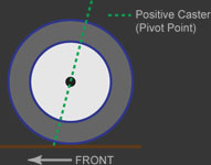
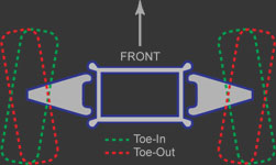
Wheel alignment is another key factor in the way a buggy will handle; the following is a brief explanation on three common factors that determine proper alignment. First is Camber: this is the vertical angle of the wheel in relation to the chassis; in other words, how much the top of the wheel tilts towards (negative Camber) or away from (positive Camber) the chassis. For a buggy application zero or slightly negative Camber is ideal since positive Camber would result in poor handling and stability. Second is Caster: this is the pivot point angle in relation to vertical; in other words, the top of the spindle leans towards the rear of the chassis resulting in positive Caster. Positive Caster will provide that steering feel due to the centering effect and straight line stability; most buggies have positive Caster ranging from 7 to 10 degrees. Third is Toe: this is measured by how much the front of the wheels point towards or away from each other. Toe-In is when the front of the wheels are closer together than the rear and Toe-Out is just the opposite; most buggies have 1/8 to 1/4 inch of Toe-In.

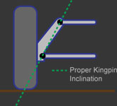
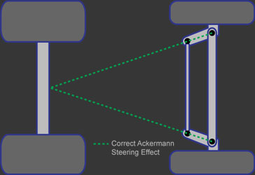
There are two other factors that affect handling that should be mentioned here. First is Kingpin: this is the axis around which steered wheels pivot; in other words, the spindle assembly is designed where the top of steering knuckle leans toward the chassis but the spindle shaft remains horizontal. This is so that when an imaginary line is drawn through the upper and lower spindle pivot points it will intersect the ground where the center of the tire makes contact. This results in the wheel pivoting at the center of the wheels contact point rather than scrubbing or pushing though an arc. Second is Ackermann Steering Geometry: this is named after Rudolph Ackermann, who designed a solution to the turning problem in London in 1817. The idea is to angle the steering arms of the steering linkage towards the center of the vehicle so that the tie rods change the wheel angles by different amounts resulting in the inside wheel taking a shorter path than the outside wheel following the correct radius without scrubbing or pushing through the turn. Calculating of the exact angle of each steering arm is complicated but angling the steering arms so that a line drawn from the centre of each arm meets at the centre of the rear axle provides the desired result.
Now that you have a better understanding of the complex engineering that goes into the proper design of a dune buggy, here is what sets Tom Pro Design Buggies above the rest by revealing the oversights we have observed on our competitor’s buggies…
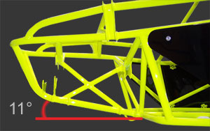
- Incorrect Suspension Geometry: Over 90% of today’s long-travel buggies have, what we call, old-school travel. To understand that, look at the pivot points on the front A-Arms; at the frame draw a straight line threw that, this is the pivot point. Now you will notice that the wheel at the bottom of the travel goes forward first, then backwards as it runs through its cycle. The best example of modern front geometry is to visualize the motion of a dirt bike; as the front wheel compresses or goes up, it moves backwards resulting in a much smoother ride over its old-school counterpart. Our models incorporate this concept by mounting the A-Arms on an 11 degree angle for proper wheel motion. Another advantage of the 11 degree mounting is there is less chance of Suspension Stall in the event the buggy is stuffed in a Witch Eye. Suspension Stall occurs when impacting the buggy at an extreme angle and the wheel is unable to travel upwards in order to absorb that impact resulting in major failure/damage.
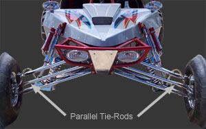
- Bump Steer: This is when the wheels Toe-In and Toe-Out as the suspension cycles up and down resulting in the vehicle steering off the intended track without driver input when hitting a bump. To minimize this effect, the Steering Rack should be properly mounted so the Tie-Rods are parallel to the A-Arms. Also, the Tie-Rods need to be the exact length of the top A-Arm plus the bottom A-Arm divided by two.
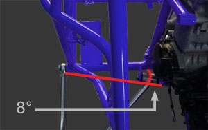
- Rear Trailing Arms Are Too Long: Our buggies have shorter Trailing Arms allowing more manipulation which provides a better forward bite and optimal acceleration; by adding more air pressure to the rear tires you can decrease this effect allowing you to slide. Shorter Tailing Arms pivot at a shorter radius resulting in improved backwards motion away from the bump. Also, our Trailing Arms on all of our models are the same length and are mounted on an 8 degree angle providing the correct geometry. With 8 degree mounting points, the Trailing Arms will create positive and negative Camber through its cycle. This is important because as the vehicle goes around a corner, it will lean into that corner yet the wheels will stay square to the ground for maximum traction and minimal sliding. When the Trailing Arms are mounted square to the frame (zero degrees) or a 5 (equal length) link system is used, like some of our competitors, the wheels will cycle straight up and down leaning with the chassis resulting in poor traction and sliding.
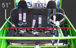
- Small Driver’s Compartment: Our driver’s compartment is the largest in the Mini Buggy industry and has more leg and head room than most full-size buggies.
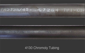
- Mild Steel Tubing: Our buggies are built using 100% Chromoly tubing providing superior strength and lighter weight. We have heard too many horror stories from owners of our competitor’s buggies who regretted not getting a Chromoly based product since the Mild Steel was, in most cases, the point of failure.
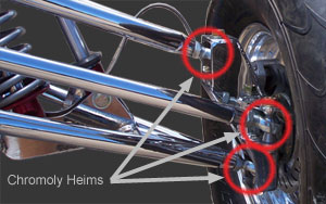
- Mild Steel Heim Joints: Our buggies are assembled with 100% Chromoly Heim Joints providing better strength and durability. Once again, the Mild Steel was, in most cases, the point of failure on our competitor’s buggies.
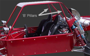
- No ‘B’ Pillars: All of our models have ‘B’ Pillars which help minimize cage collapse in the event of a roll-over.
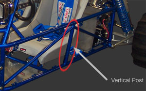
- No Center Chassis Vertical Posts: Our buggies have vertical posts from the seats to the mid-rail providing support for the driver and passenger weight.
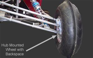
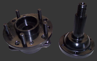
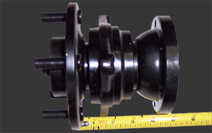
- No Front Hubs: Spindle mounted wheels are offset which creates improper steering geometry and require shorter A-Arms; our buggies come standard with billet aluminum hubs which allow us to use longer A-Arms due to the 3 inch backspace on the wheel providing increased travel with correct geometry. Also, our buggies have the longest A-Arms providing less scrub and angle at the pivot points.
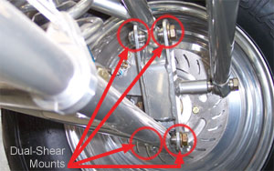
- Single Shear Spindle Mounts: If that fails the buggy will flip over; our buggies are fabricated using dual-shear mounts in order to reinforce the front-end from those unexpected hard impacts.
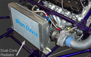
- Single Core Radiator: Our buggies come standard with a Ron Davis dual-core aluminum radiator with a shroud and thermo-controlled electric fan for extremely efficient cooling.
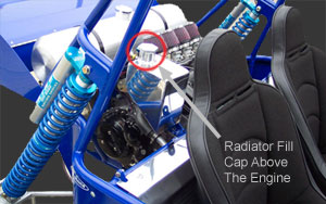
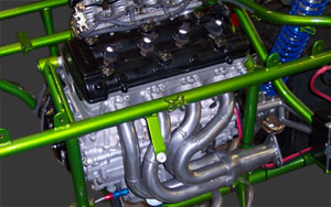
- Radiator Fill Cap Not Above The Engine: This can trap air in the cylinder head resulting in critical overheating; our buggies come standard with a custom fabricated aluminum reservoir that is mounted above the engine eliminating this problem.
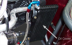
- No Oil Cooler: Our buggies come standard with an Oil Cooler and connected to the engine via custom fabricated billet aluminum adapters and stainless steel braided lines, providing more efficient cooling.
- Exhaust Wrapped Around The Cylinder Head: This can cause overheating since that extreme heat needs to exit away from and not around the engine; properly routed exhaust can increase horsepower and improve performance.
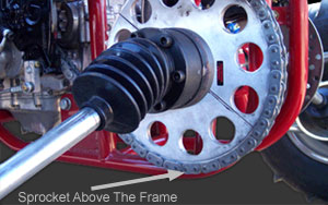
- Large Rear Sprocket Exposed Below The Frame: This can cause the chain to break and damage to the sprocket in the event you go over a rock or some other hard surface; our buggies have the Sprocket positioned above the frame protecting it from those hazards and with our custom Reverse Box, it is positioned even higher.
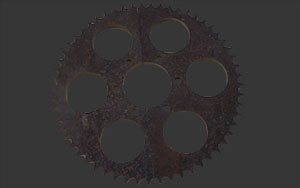
- Aluminum Rear Sprocket: These are not very durable for a dune buggy application resulting in premature failure; our buggies come standard with an AR400 Sprocket made of hardened tool steel and .050” thicker to provide better support for the chain pins/rollers resulting in longer chain life.
- Stub Axles: Stub Axles are an older design that are not only used as a carrier for the spinning rear wheels but also carry the weight of those wheels directly on the shaft. Our buggies use Micro-Stubs which only carry the spinning rear wheels and the weight is carried by the bearings, minimizing the stress on the shaft and potential failure. Other advantages with using Micro-Stubs, because they have shorter shafts, we are able to use longer drive axles with less angle providing more real wheel travel.
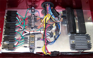
- Electrical System Wired With Butt Connectors And No Relays: Our buggies’ electrical system is completely soldered and shrink tubed with relays for all components for a proper transfer of electrical currents and loads.
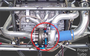
- Incorrect Turbo: Most of our competitors use a Street Bike Turbo which are Bushing type and too large. For a dune buggy application, a smaller Ball Bearing type Turbo is ideal, especially due to the additional weight of a dune buggy chassis; this will provide less lag with increased boost response and the Ball Bearings provide longer life in the sand.
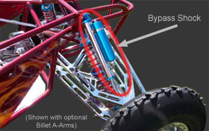
- No Bypass Shocks: It is a common misconception that Bypass Shocks are not necessary on such a lightweight vehicle when, in fact, that is quite the opposite. The obvious goal of a long-travel vehicle is to minimize the up and down motion of the chassis by forcing the wheels to take on that role. A heavier vehicle makes more force in order to counteract the gravitational force keeping it down; where as a lighter vehicle is much more susceptible to bumps; this is where Bypass Shocks allow for running softer springs reducing the resistance in the wheel motion, allowing them to move before the chassis but without sacrificing adequate absorption of varying terrain. Building a vehicle just for jumping is easy since that is a single impact at a time; the real science goes into creating a vehicle that can also handle multiple consecutive bumps with minimal up and down motion to the chassis; Tom Pro Design has achieved this in our buggies; take a look at the ‘Suspension Action’ video in our Gallery.
We realize this is a lot of information to absorb but we feel it is important to educate our potential customers who are about to make a major investment in a product and that should be done armed with all the facts and no regrets. So what are you waiting for? Give us a call today to place your order for a Tom Pro Design Buggy, The Baddest Mini Buggies on the Planet.